Ground Frame Modular Installation
OVERVIEW
The Ground Frame Foundation System provides a solid, stable, and efficient foundation that captures and preserves the supporting strength and natural functions of the Earth’s soil and provides a connection to the structure above.
IMPORTANT NOTE:
- Prior to commencing work, all installations must be reviewed by Ground Frame engineering team or the project engineer of record.
- Ensure all permits have been obtained.
- Check for buried utilities, mark on site as per local building codes.
- Have all required tools and equipment outlined below.
- Wear proper safety gear.
Safety Glasses

Ear Protection

Steel Toe Work Boots

Rubber Insulated Gloves
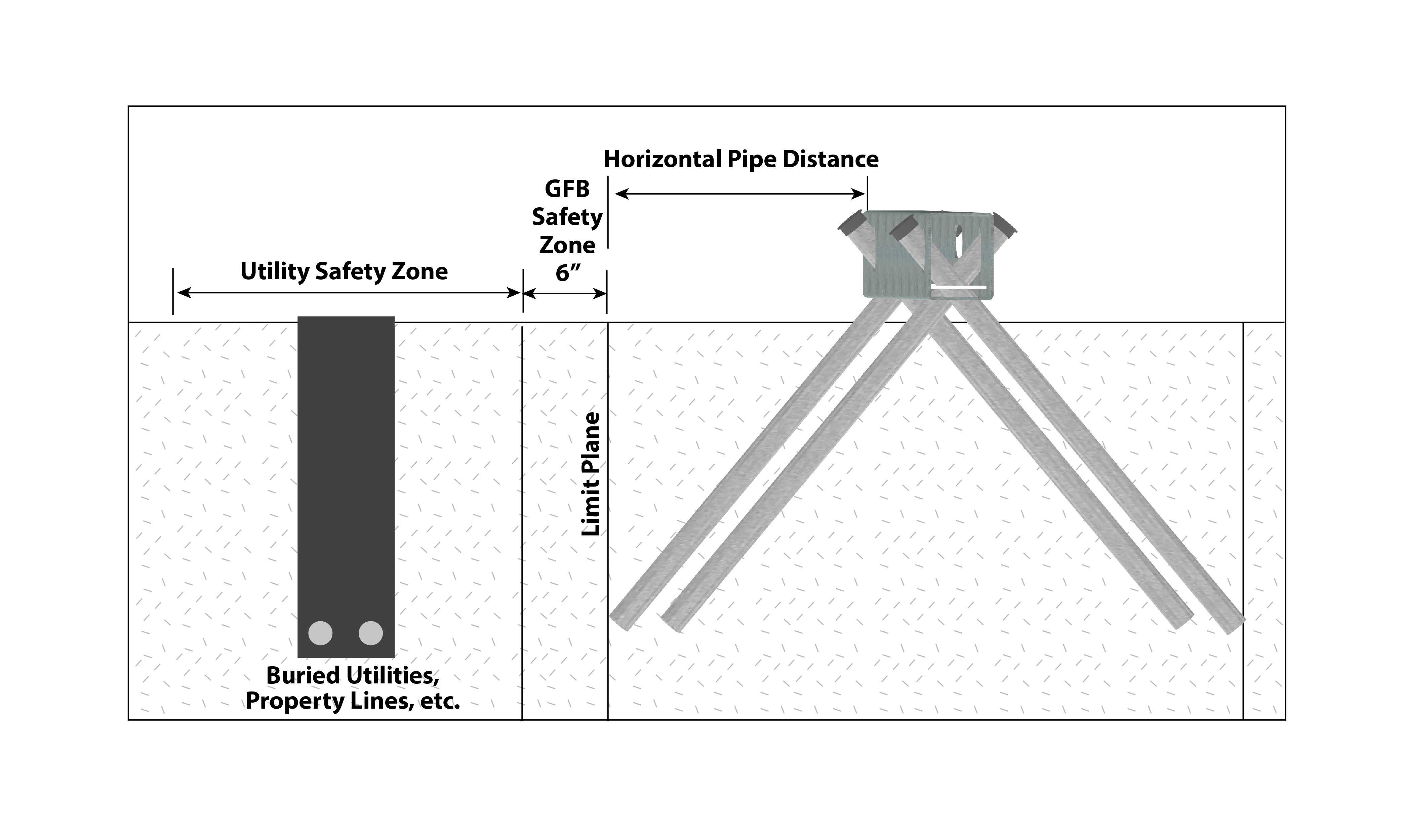
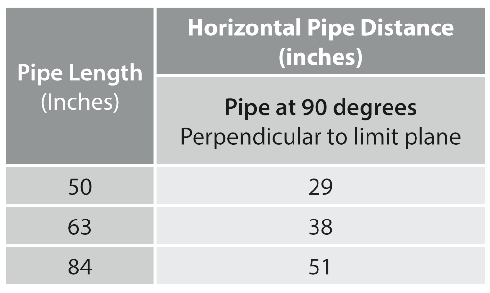
Horizontal Pipe Distance
Measured from horizontal center of anchor bolt to vertical pipe end limit
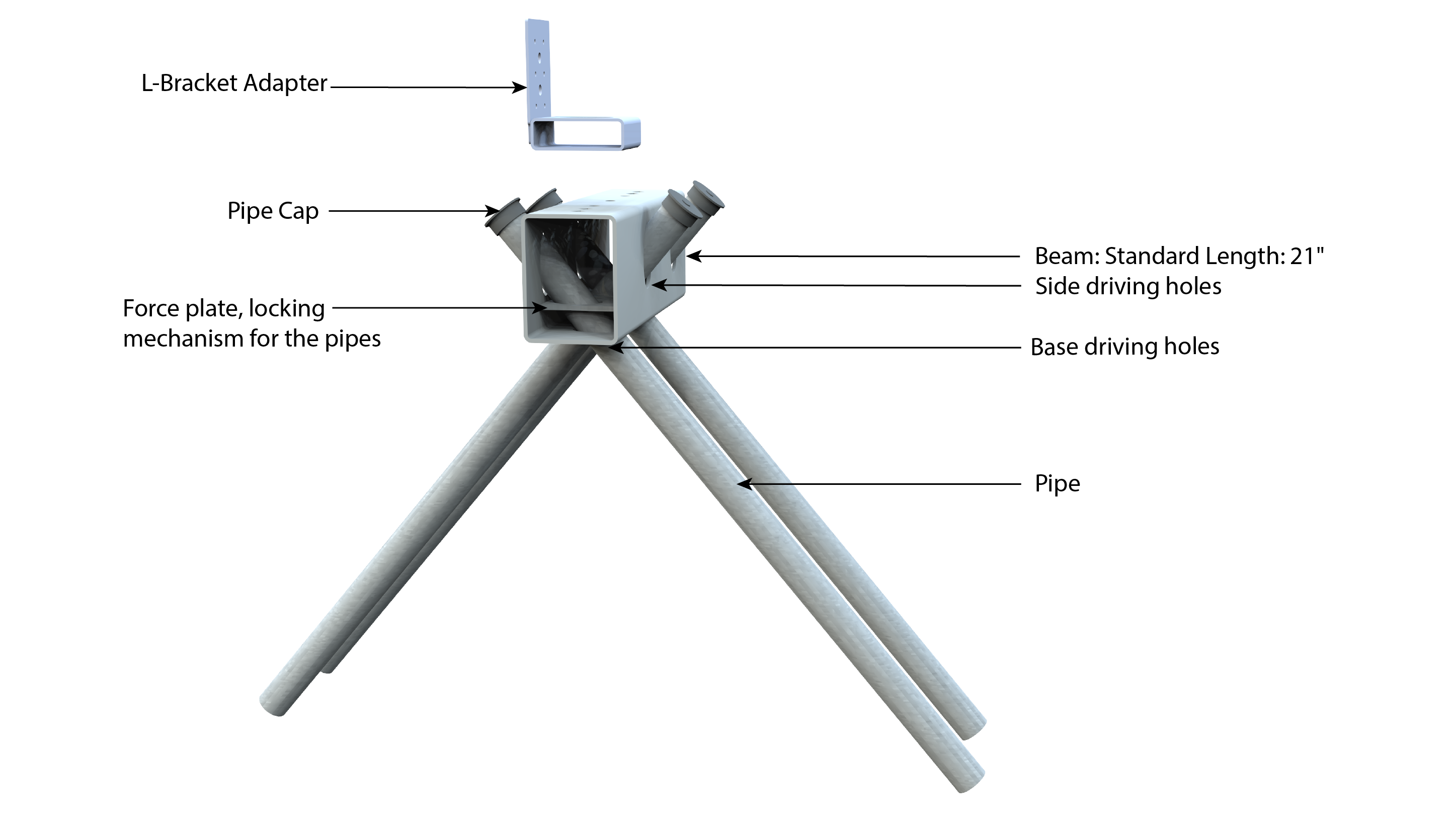
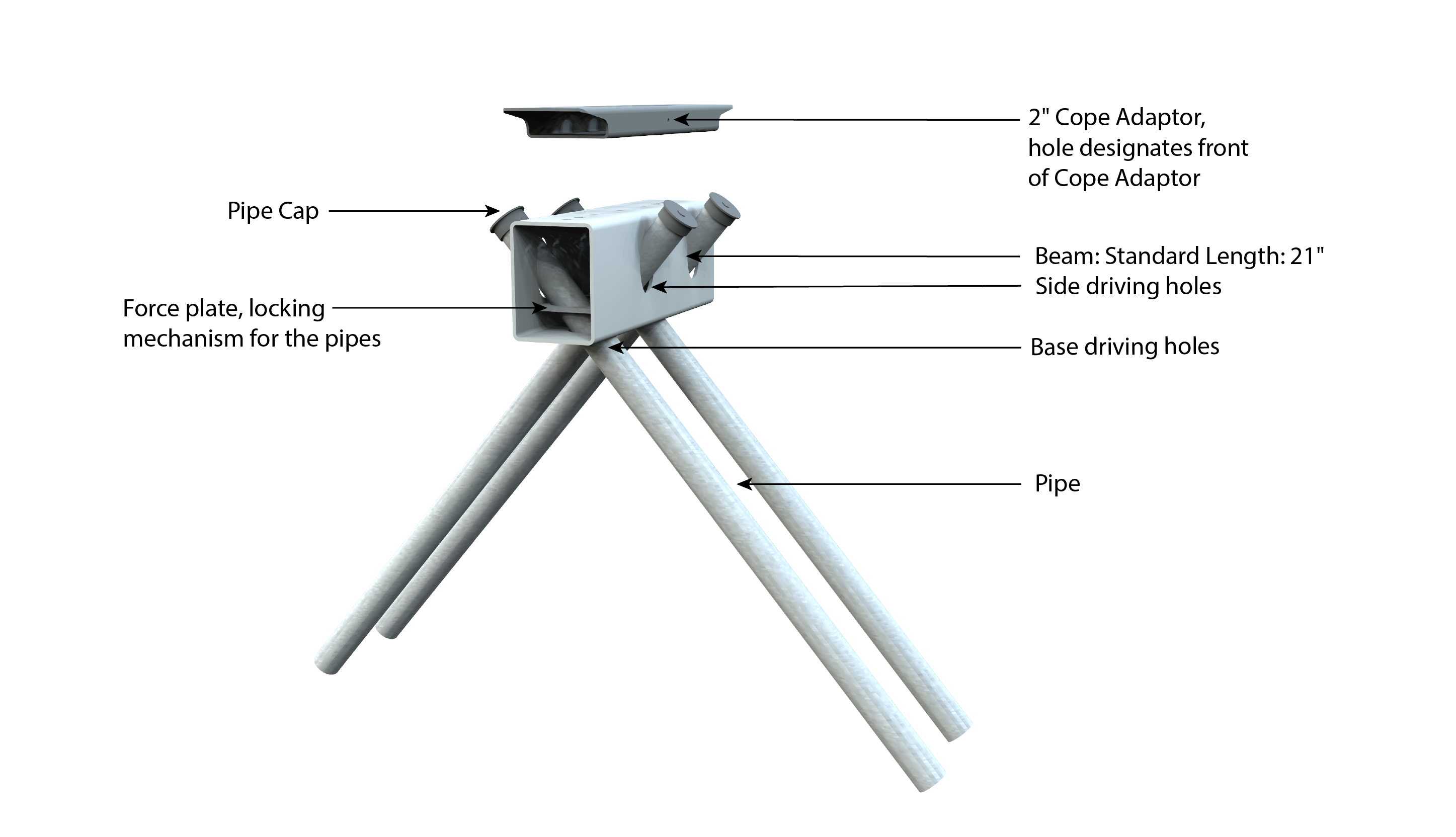
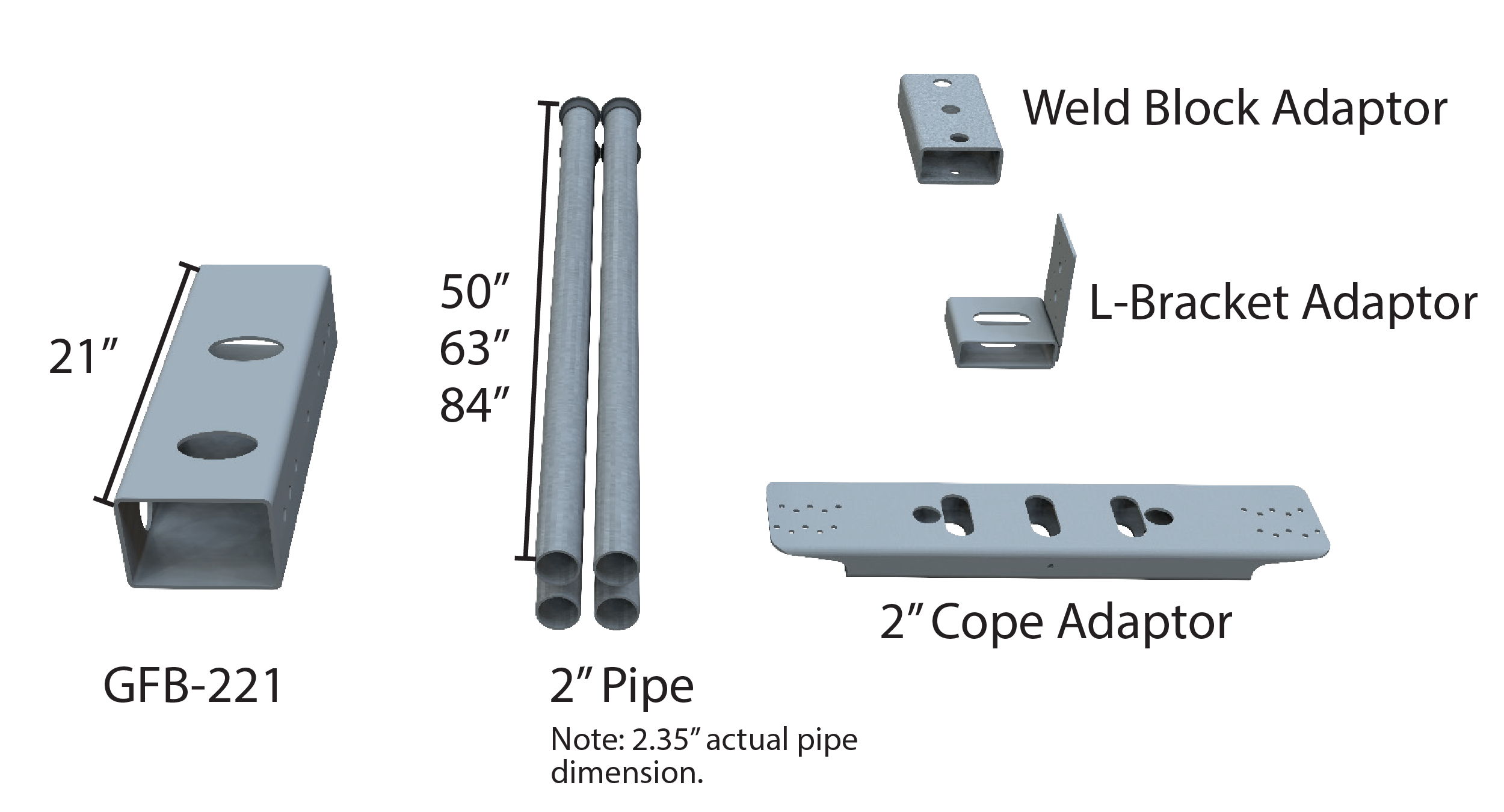
GROUND FRAME BEAM AND L-BRACKET ADAPTOR OVERVIEW
GROUND FRAME BEAM AND COPE ADAPTOR OVERVIEW
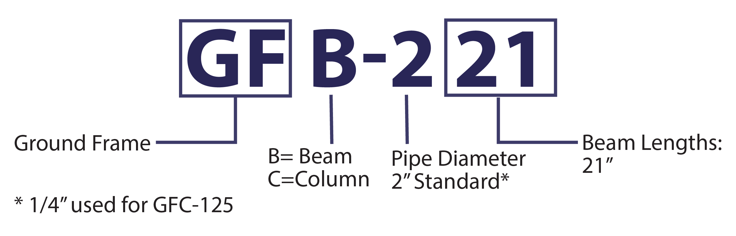
GROUND FRAME SMART PART NUMBERS
Simplify field inventory checks using our smart part numbers.
REQUIRED CREW AND TOOLS

Minimum three-person crew for beam installation, two-person for column
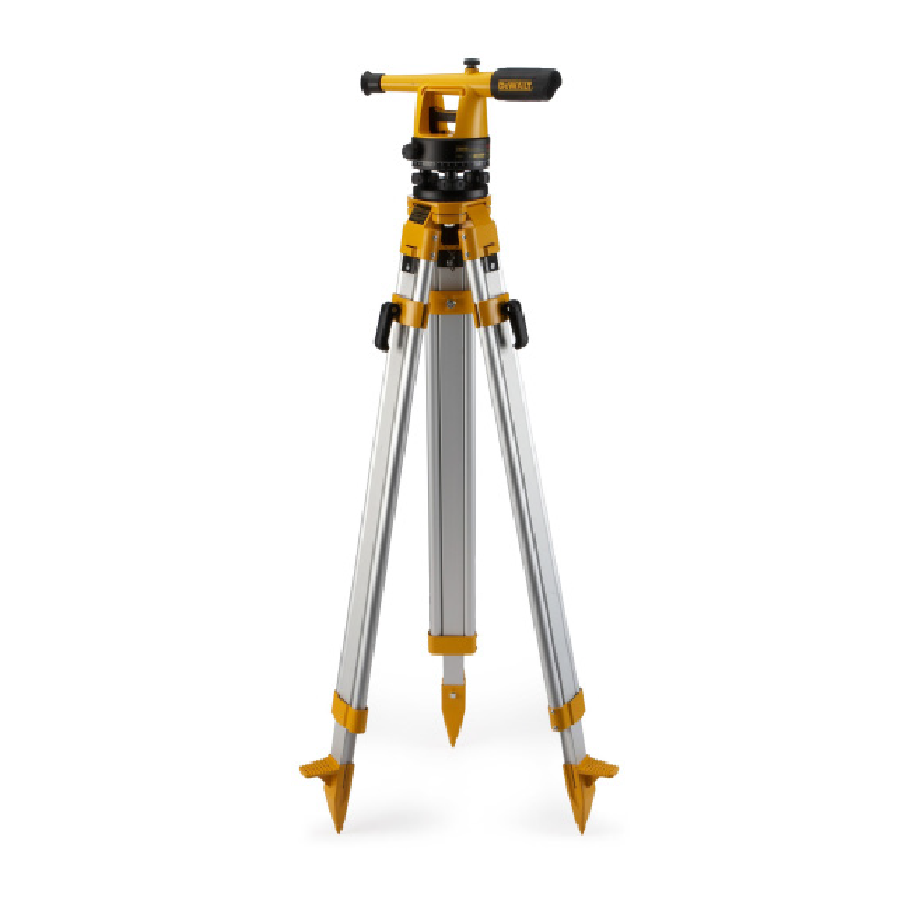
Site transit level
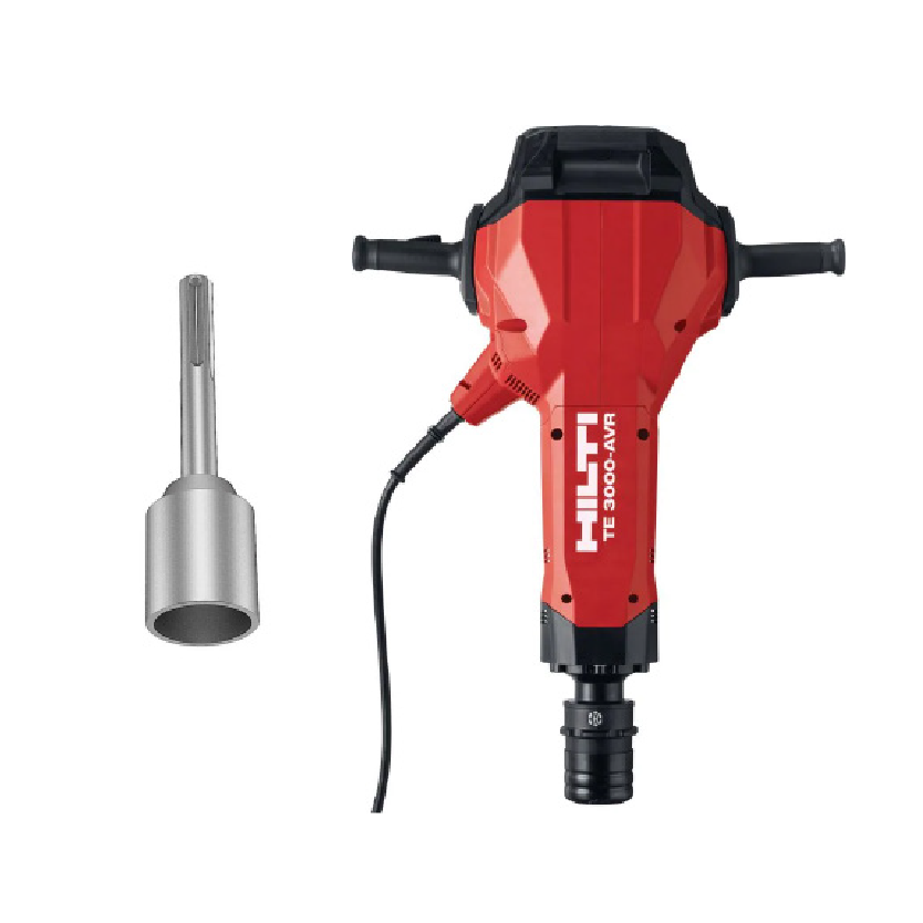
Electric driving hammer (recommended TE-3000 AVR) with driving bit
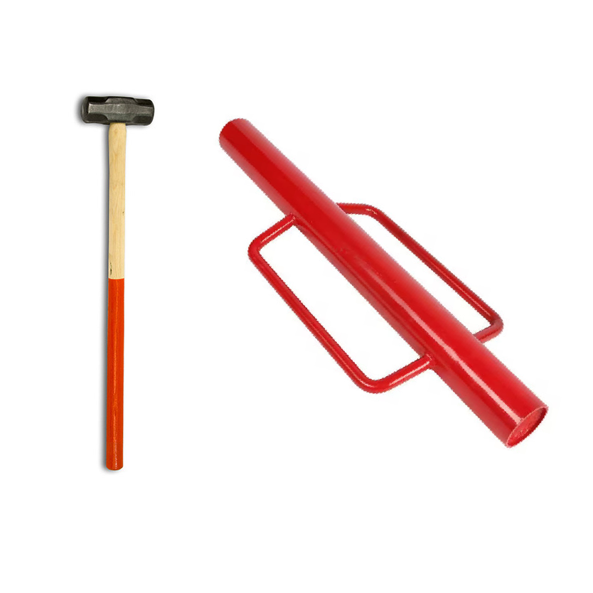
Sledgehammer or post driver
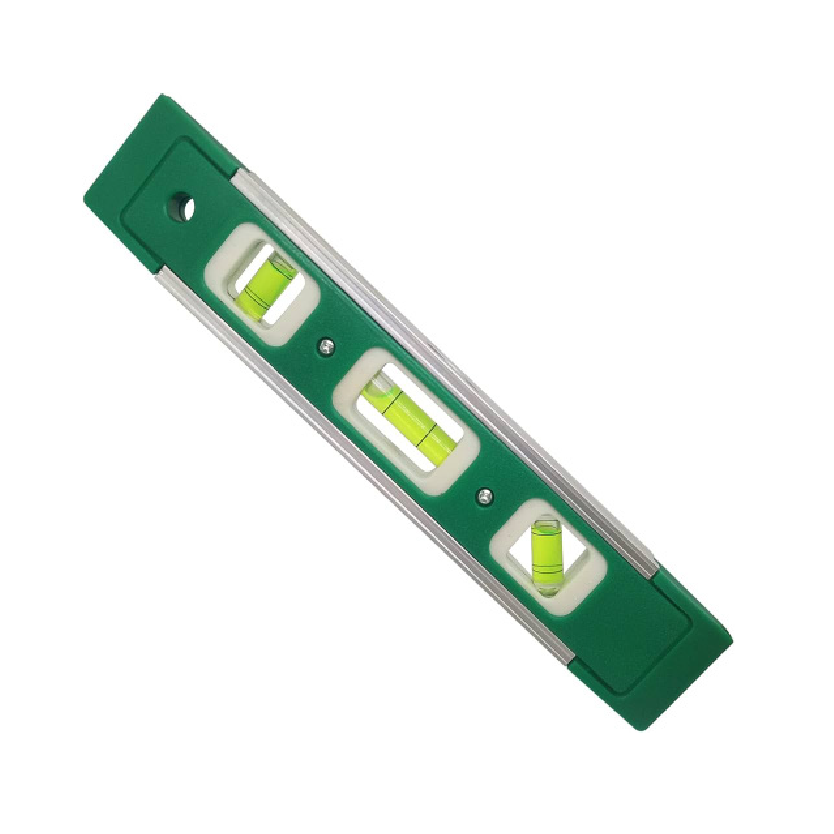
Small level with magnetic edge
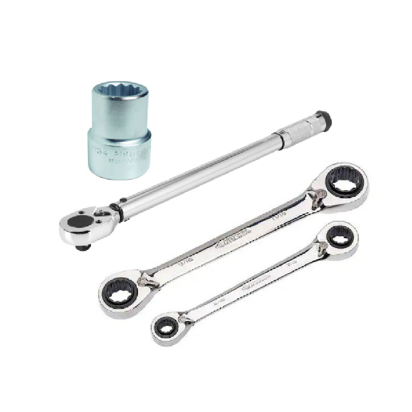
Torque wrench, Socket, Ratcheting wrench

Drill and impact driver
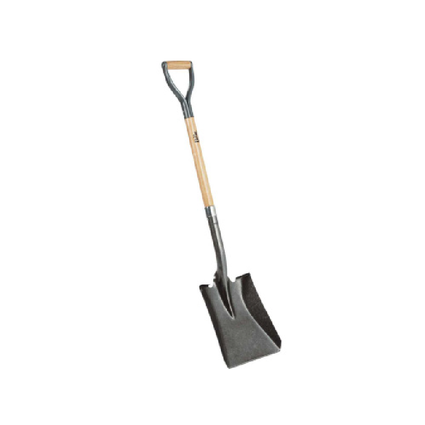
Square-edge shovel required for column installation
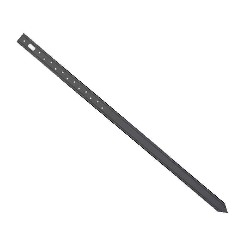
Steel Stake (36″ length)
(Use for batter boards and for plumbing beams)
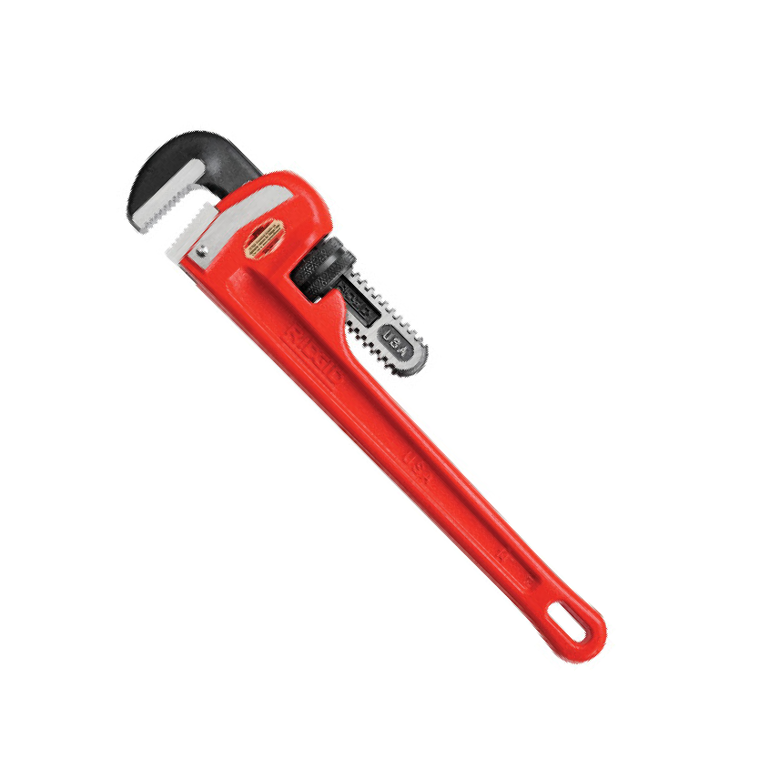 2 Pipe Wrenches
(Use heavy duty pipe wrenches that will go over the outside diameter of the pipe)
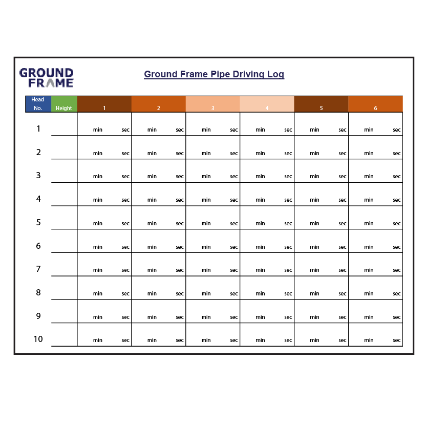
Driving log
Download Driving Log Template
BEFORE YOU BEGIN
Check Pipes for Proper Slide
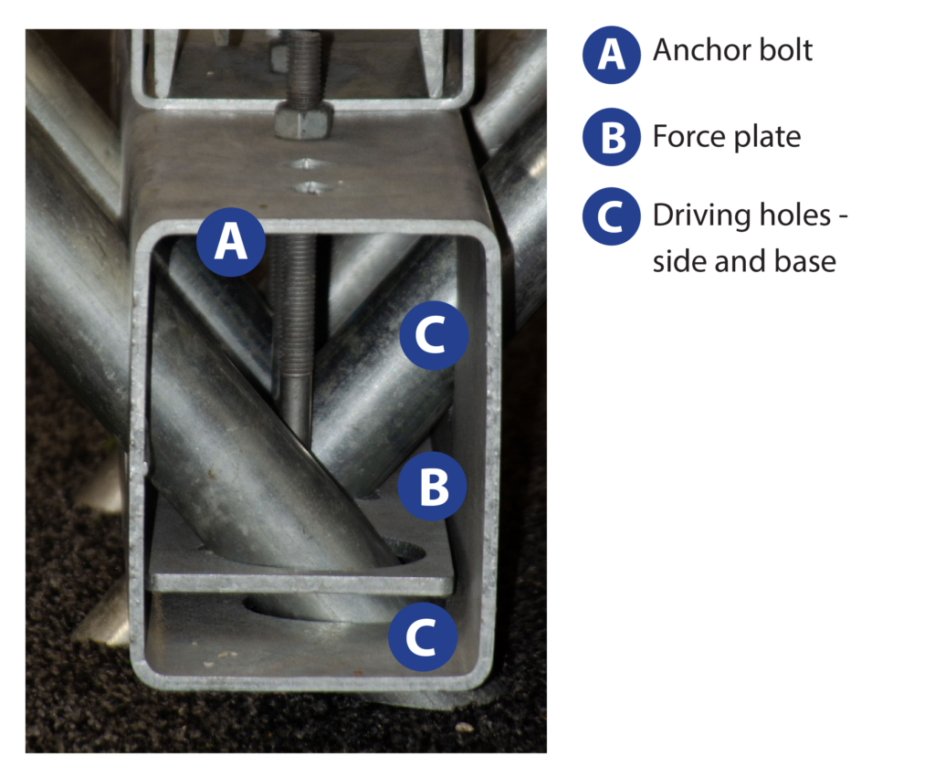
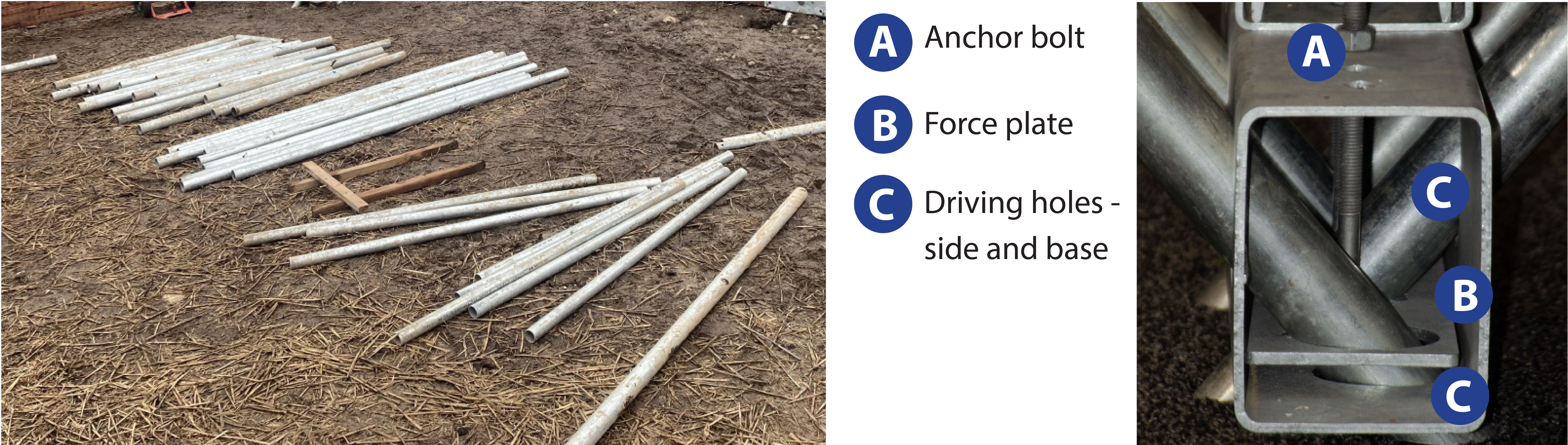
The anchor bolt and force plate are factory set for proper pipe slide, but may have altered during shipping and handling.
Pipes should easily slide through holes. If pipes do not easily slide, loosen locking bolt. Do NOT force the pipes through the beam/ column holes.
If the bolt is fully loosened and the pipes do not easily slide, contact Ground Frame customer service.
| Do | Don’t |
| Follow the instruction in this guide. | Proceed without reading this guide. |
| Check all local building regulations before you begin. | Don’t assume local building regulations have been checked. |
| Use only specified hardware. | Substitute hardware. |
| Review troubleshooting tips to safely remove pipes or adjust pipes. | Force pipes past obstructions. |
| Weld directly to the beam. Beam is galvanized and has structural integrity, never weld directly to the beam. Always use provided parts such as a weld block as your welding surface. |
SITE PREPARATION
1. Clear and level site as per approved plans. Ensure proper site drainage and desired floor height.
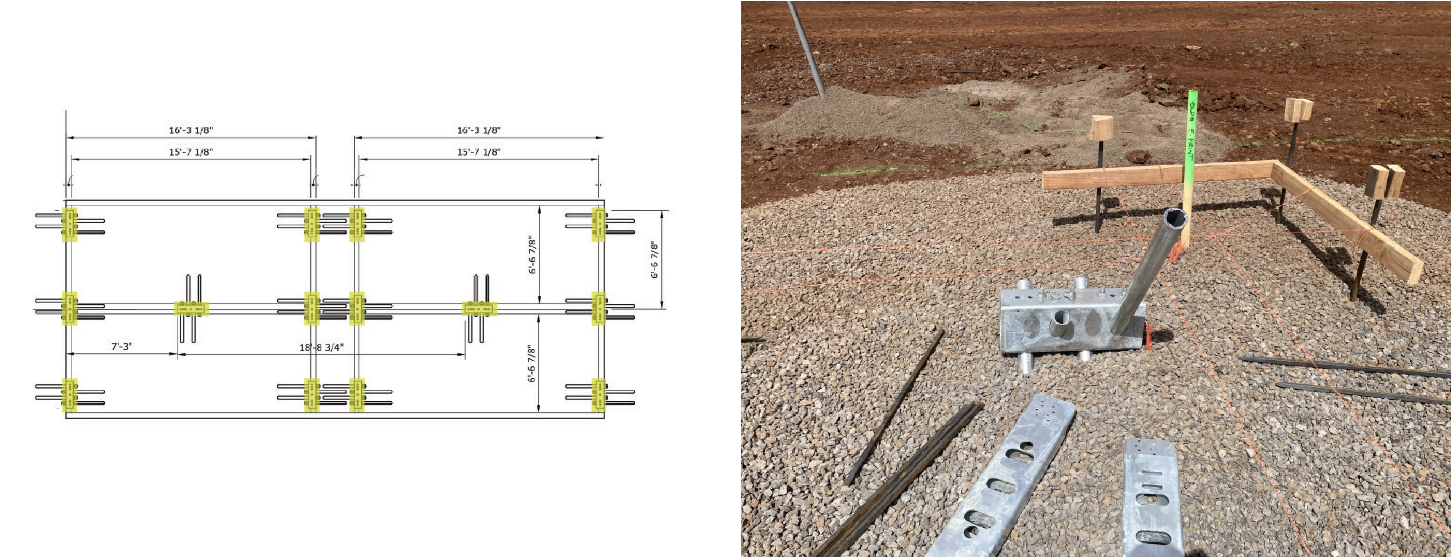
2. Using the dimensioned layout as a guide, establish the building border with a string line.
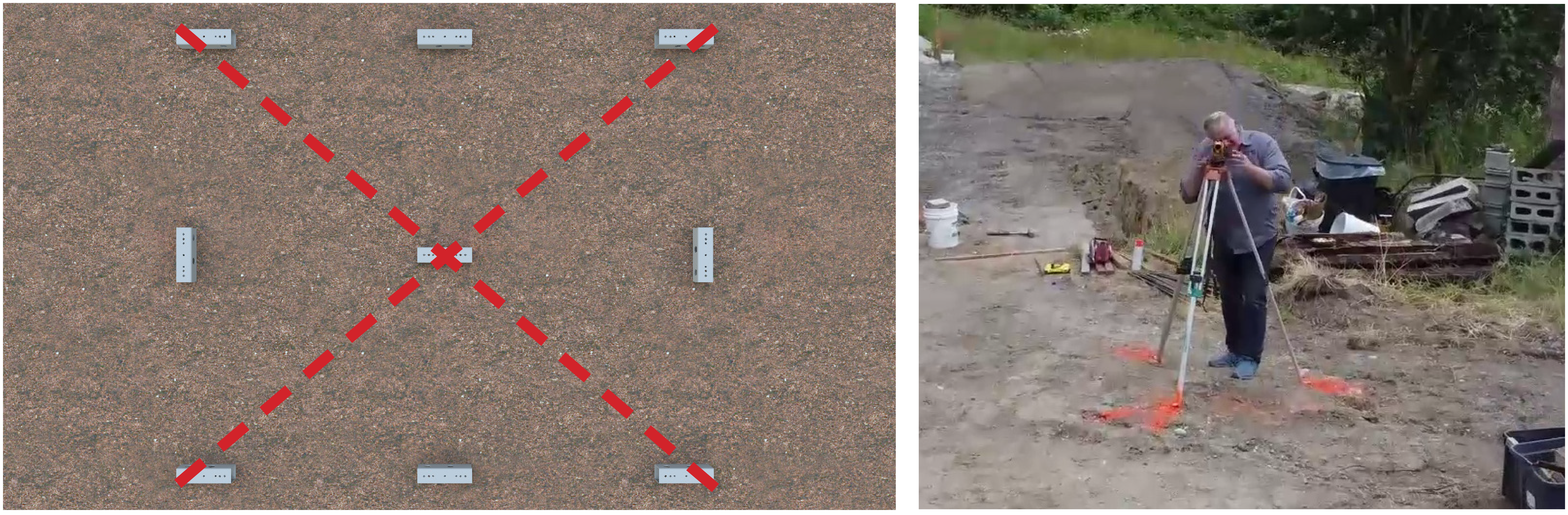
3. Measure diagonally to ensure the border is squared.
4. Find the elevation of a “Master Corner” (the highest corner).
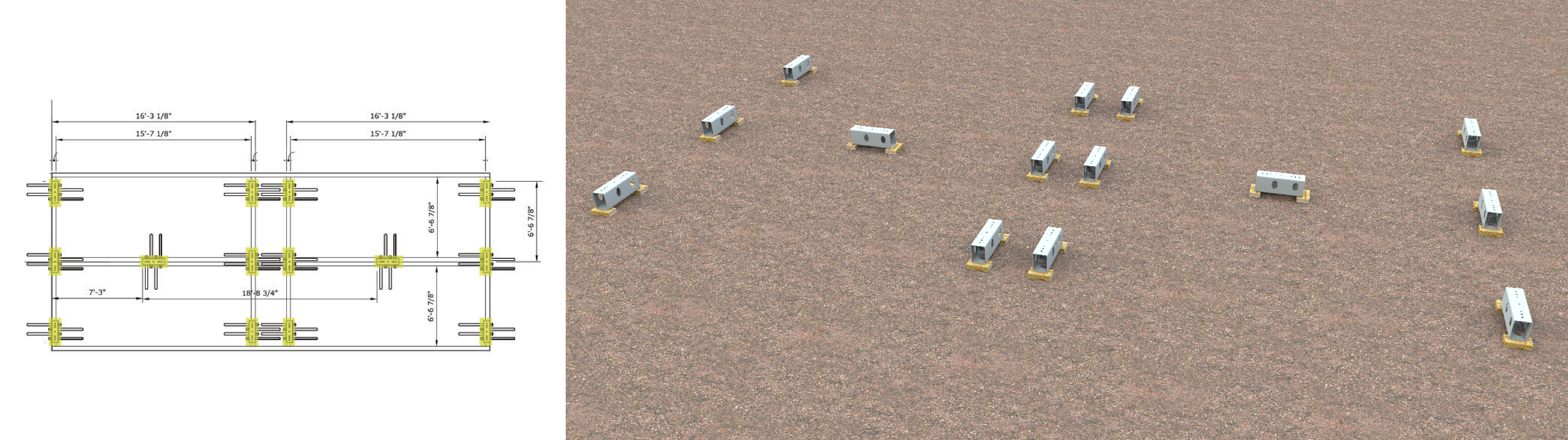
5. Using the dimensioned layout, roughly stage the Ground Frame steel beams. It is best practice to start in the corners.
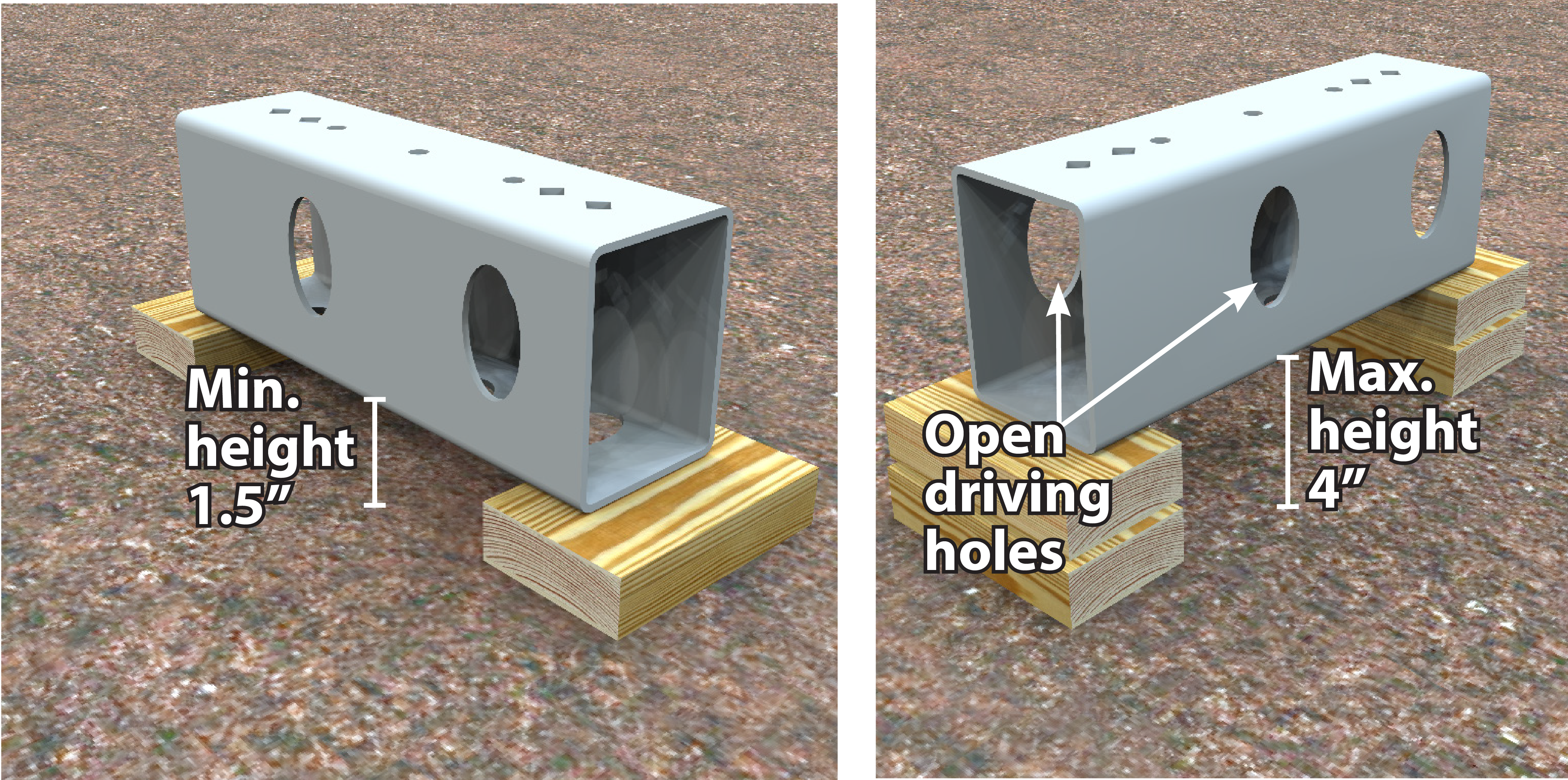
6. Block and shim the end of steel beams to the same level as the master corner. Minimum block height is 1.5” from master corner.
7. Maximum block height is 4”. Ensure driving holes remain open and are not blocked by shims.
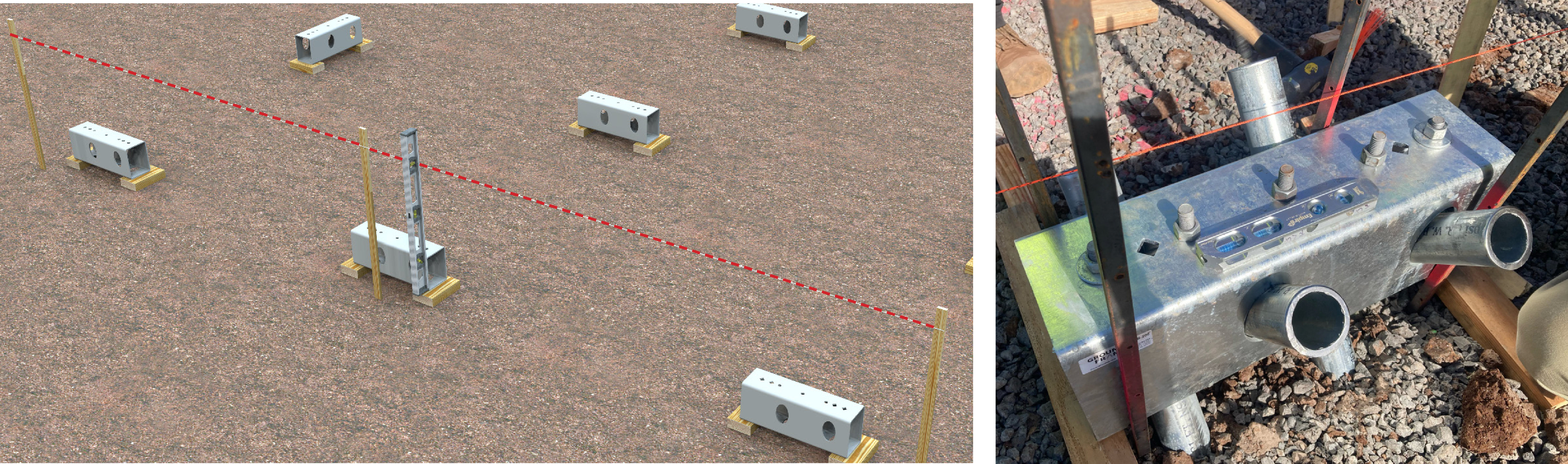
8. Verify all outer dimensions according to the dimensioned layout. Ensure steel beams are plumb, level, and square to the overall layout.
Best practice is to cradle the beam with 4 stakes to ensure it stays on layout when driving pipes.
PIPE INSTALLATION
![]() Ground Frame strongly recommends using a two-person crew for pipe driving.
Ground Frame strongly recommends using a two-person crew for pipe driving.
Ground Frame pipes are not refusal driving systems. All pipes must be driven to their full length to provide specified bearing, uplift and lateral capacities.
9. Upon leveling completion, gather and stage Ground Frame pipes.
10. Ensure the pipe can easily slide through the side driving hole.
Important Note: If pipe does not easily slide, loosen the nut (on top of beam), lowering the force plate.
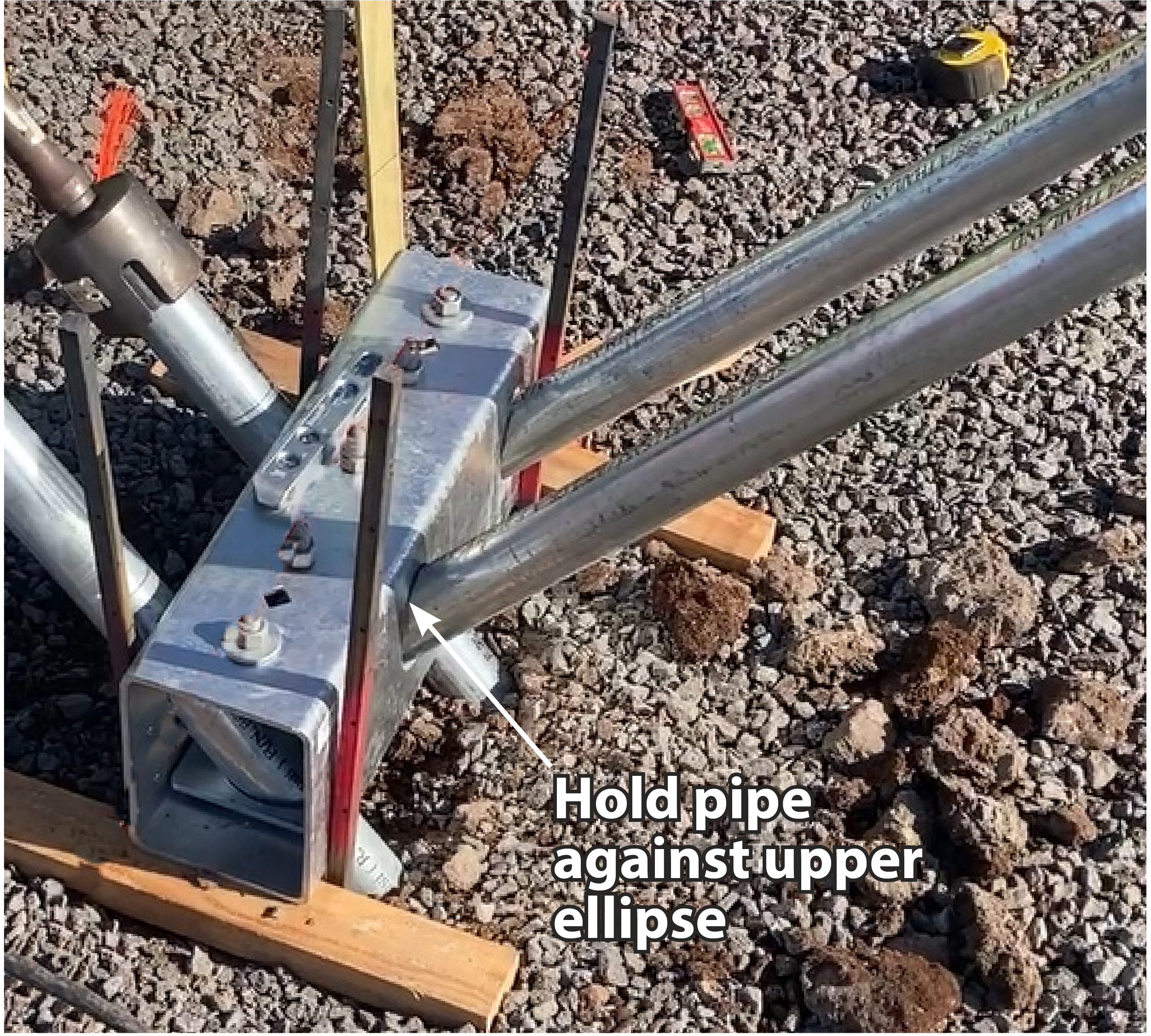
11. To ensure the pipe maintains the proper angle, hold it against the upper ellipse of the side driving hole.
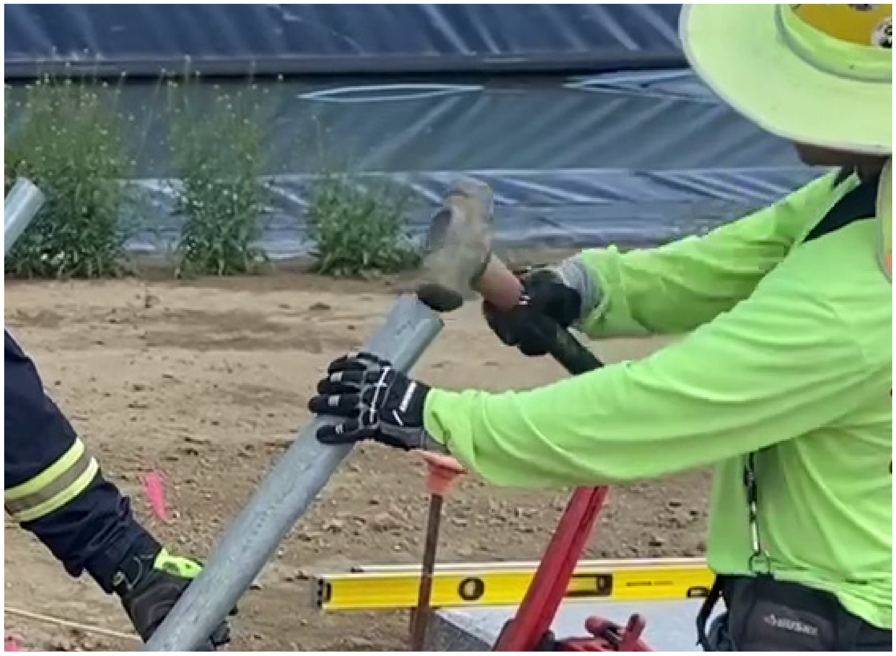
12. Using a sledgehammer, drive the pipe in a few inches, to maintain the proper angle.
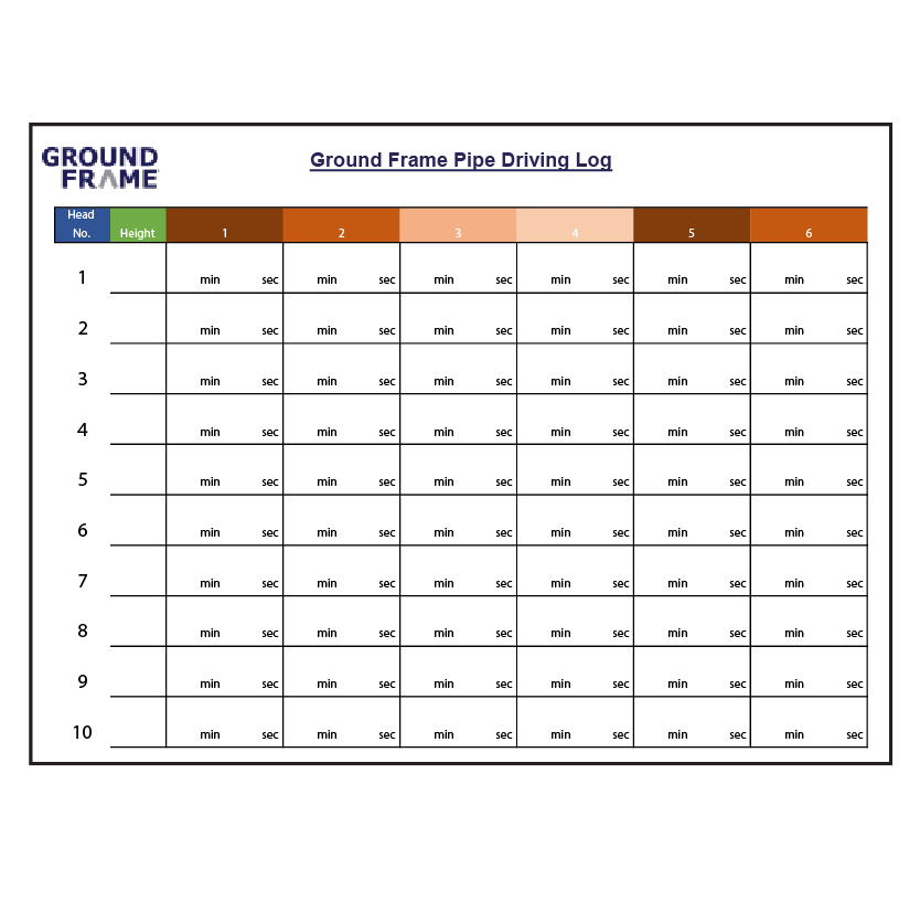

13. Prepare the driving log.
Download Driving Log Template
14. While holding the pipe up, drive the pipe through the side driving hole, using the jackhammer with the pipe driving bit.
Note: Recommended using the Hilti TE-3000 AVR electric jackhammer for driving pipes.
15. Stop driving prior to bit hitting the beam.
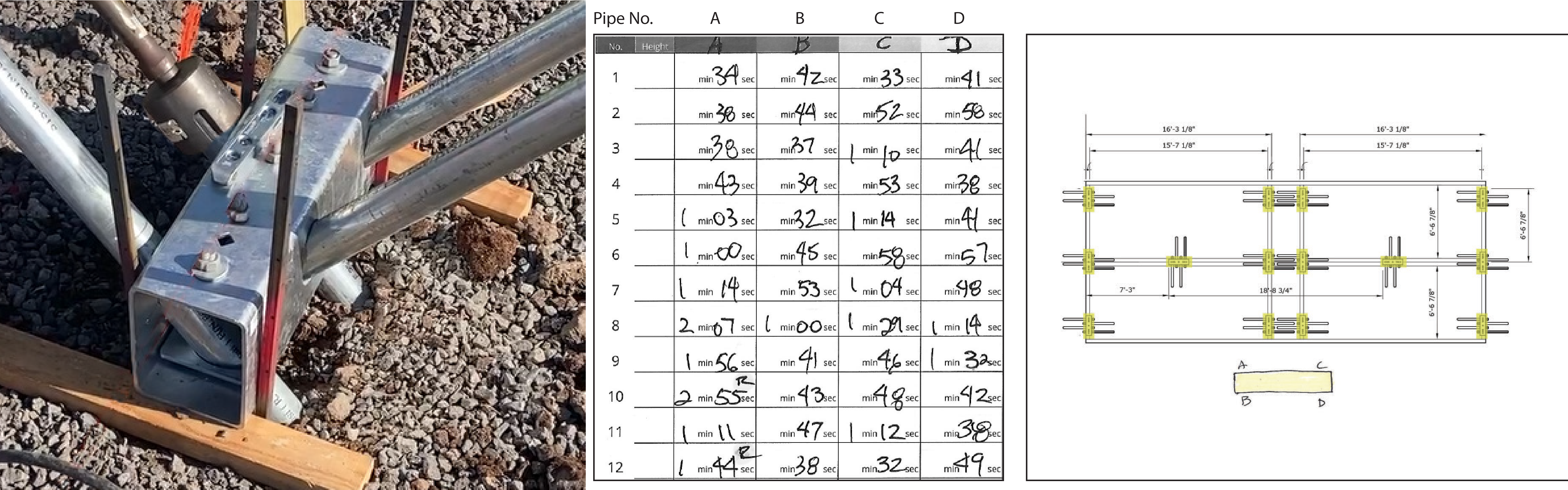
16. After each pipe installation note time in driving log.
Tip: Take dimensioned layout, number each beam, and denote the driving time for each side of the beam (A, B, C, D).
17. When pipe hits an obstruction, follow the troubleshooting steps found below.
18. Install pipe caps on top of each pipe.
![]() Cripple walls may be required based on your site conditions.
Cripple walls may be required based on your site conditions.
Walls must be designed, engineered and approved.
TROUBLESHOOTING
SHALLOW OBSTRUCTION: ~1/3 Pipe Length in the Ground

1. Remove pipe.
Tip: Simultaneously spin and pry pipe, using two pipe wrenches with two people.
2. Remove obstruction and recompact soil in 6” lifts.
3. Redrive pipe.
DEEP OBSTRUCTION: 2/3 Pipe Length in the Ground
1. Using a sledgehammer, strike the pipe, 3-5 blows, to ensure pipe refusal.

2. Cut the remaining portion of the pipe, above the Ground Frame beam, and cap.
Important Note: Indicate the length of the pipe that was cut off in the driving log.
Denote refusal (R) and indicate length of pipe that was cut.
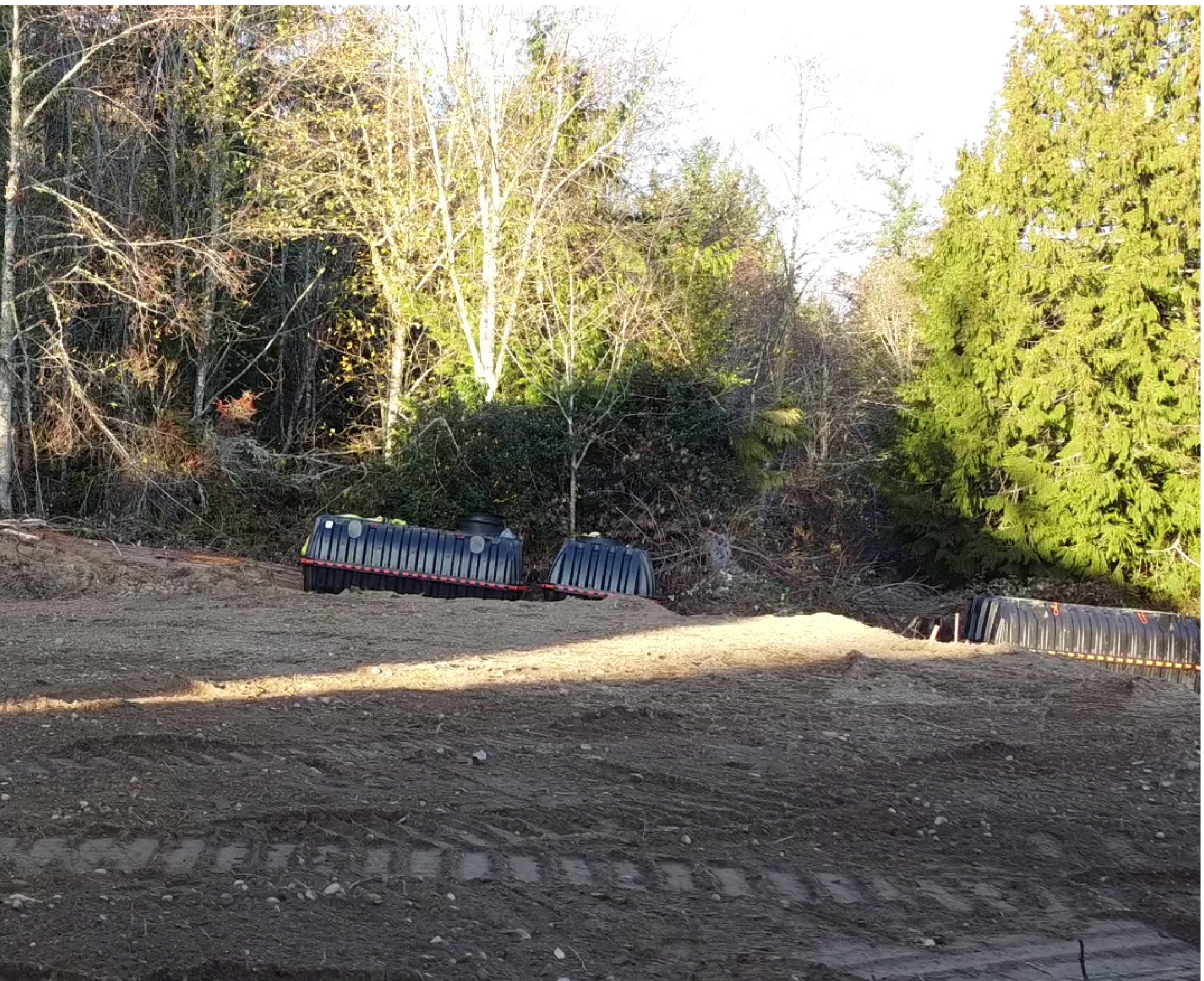
Cope and L-Bracket Adaptor Addendum
Depending on site conditions, such as sloped site, Cope and L-Bracket adaptors may be required in conjunction with continuous or small cripple walls. Outlined below are best practices to work with an approved Ground Frame engineered solution.
![]()
All cripple walls MUST be engineered to site conditions and approved by Ground Frame. Engineering would include, but not limited to: wall height, attachment to cripple wall on Ground Frame beam, and bracing.
 This slightly sloped site is using both Cope and L-Bracket Adaptors along with 21″ Ground Frame beams and small cripple walls.
Top Right: Small cripple wall with Cope Adaptor, built on site to engineered specifications
Bottom Right: Small cripple wall with L-Bracket
BEST PRACTICES: COPE AND L-BRACKET ADAPTOR ADDENDUM
 Verify cripple walls are aligned with string line. Ensure they are square and plumb to overall layout.